Landing caveats – Considerations on how to get on the ground safely.
- Andreas
- Feb 22, 2021
- 9 min read
The “softness of touchdown” or passenger’s applause are certainly NOT valid rating scales for the quality of a landing. In fact, a good and safe landing begins long before departure and many things boil down to “knowing the numbers”. What numbers matter most and what to look for will be discussed in this article. The principles apply to a variety of aircraft, for the examples the article considers commercial jet transport under EU-OPS.

Before departure: Dispatch criteria
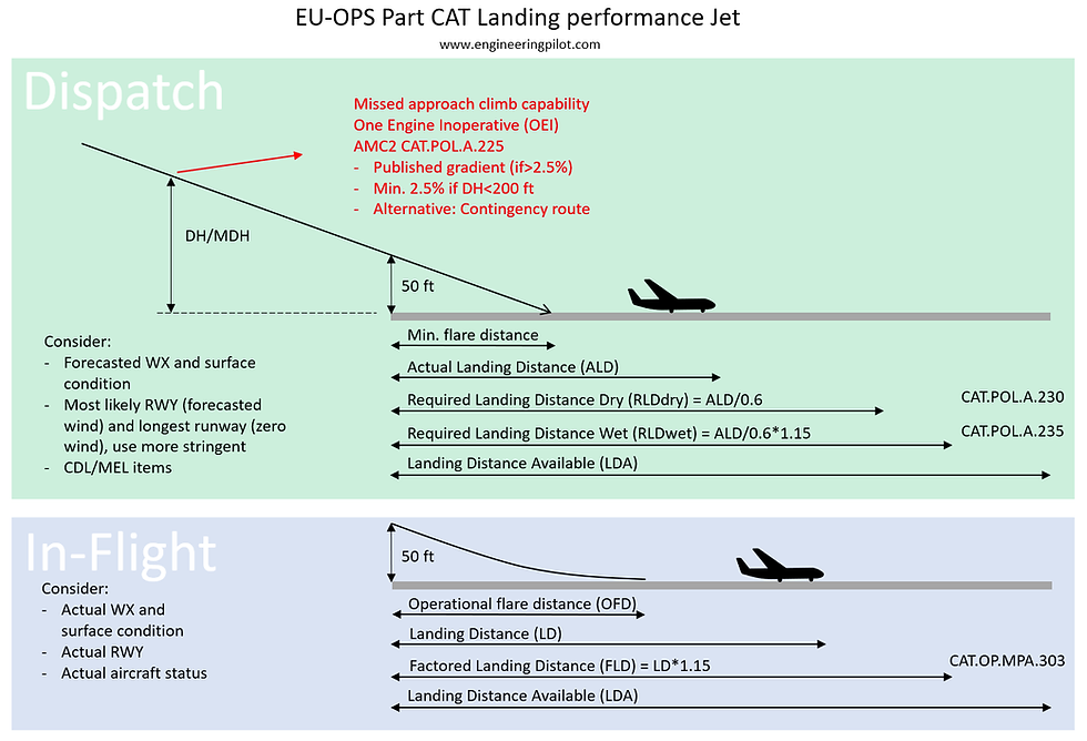
EU-OPS dispatch criteria are generally well-known amongst commercial pilots, nevertheless they are added here for completeness. Figure 2 summarizes the EU regulations and provides references to the relevant paragraphs. Some aspects are worth highlighting [1]:
Missed approach (AMC2 CAT.POL.A.225) If a climb gradient of more than 2.5% is required, the operator should check that the aircraft meets the published gradient with One Engine Inoperative (OEI), or alternatively propose a contingency route to the authorities.
Actual landing distance (ALD) Data provided by the aircraft manufacturer often reflects “minimum flare touchdown”. This is not realistic for daily operation but is “compensated” by the “60%-rule” used to calculate the Required Landing Distance (RLD) during dispatch. Note, that this is different for the in-flight calculations: Here the flare-distance is more realistic, but the margin is reduced.
Forecasted weather (GM1 CAT.POL.A.230) Two calculations have to be made: 1. Landing performance on the most favorable (e.g.: the longest) runway with zero wind. 2. Landing performance on the most likely (ATC, WX) runway with the forecasted wind. The dispatch performance is limited by the more stringent result.
In-Flight: Another landing distance calculation
For a couple of years now, commercial operators have been using in-flight landing distance calculations. The main driver behind the introduction of in-flight landing distance calculations was the inadequate prediction of the landing distance by the dispatch rules, especially for wet and contaminated runways. Figure 2 depicts how the in-flight calculation differs from the dispatch conditions. In summary, the actual weather, runway condition and aircraft status are used together with a realistic flare distance provided by the aircraft manufacturer. This leads to a fairly accurate Landing Distance (LD) and only a 15%-margin is added to get the Factored Landing Distance (FLD). Under normal conditions, the FLD must be less than the Landing Distance Available (LDA) [1]. For abnormal situations, some manufacturers and operators permit an FLD greater than the LDA, provided the LD is less than the LDA [2] (See Figure 2). In other words: For emergency situations, compromising the “15%-margin” is permitted by some manufacturers/operators.
Runway condition: Goodbye “MOTNE”, hello “GRF”
European pilots used to “MOTNE” format and friction coefficients, are in for a change in November 2021! The ICAO Global Reporting Format (GRF) will be introduced, one year later than planned due to Covid-19 [3].
Note: In the US, the Field Condition Notams (FICON) are essentially an application of the GRF and therefore US pilots will already be familiar with the terminology.
Generally, the ICAO GRF brings a change in philosophy in the sense that the runway condition is primarily assessed by trained personnel and relies less on pure “friction coefficients”. Friction measurements continue to be used as an option, but results are converted to a simple number (0-6) corresponding to the Runway Condition Code (RWYCC) of the Runway Condition Assessment Matrix (RCAM), when reported to flight crews.
The “MOTNE”-format for runway condition in METAR’s and the reporting of friction coefficients will be discontinued [5] [7] [9].
Figure 3 below depicts the new data distribution process in Europe. The relevant regulations and guidance material are listed in the grey boxes.
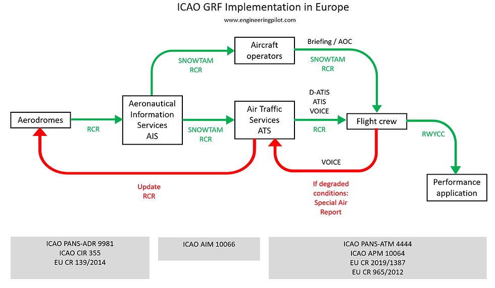
The introduction of ICAO GRF should make runway condition assessment easier for flight crews and also streamline the process of performance calculation. Note, that operating manuals and tools might need to be adapted to reflect the new format.
SNOWTAM during summer?
Yes, we might see SNOWTAM during the summer period, as they will also be published for standing water > 3 mm to promulgate the runway condition [5]. New maximum validity of a SNOWTAM will be 8 h. The layout will be changed slightly and will consist of two sections as depicted in Figure 4:

Important: As a convention, the RCR published in the SNOWTAM reflects the lower runway designator, regardless of the landing direction. If the RCR is promulgated to a flight crew (ATIS, D-ATIS or voice), it must reflect the operational runway in the landing direction [4][6][7].
Below is an example of a new format D-ATIS. Note that the runway designator is the operational runway (25, not 07) and the runway condition is given in the landing direction:

Approaching the threshold: PAPI/ILS alignment and MEHT
A 3°-PAPI with a 3°-ILS, no big deal? Hang-on! There is much more to it that a simple angle!
PAPI background: MEHT
The PAPI siting requirements stipulated in ICAO annex 14 demand a certain minimum wheel clearance at the threshold for the lowest “on path” indication [10]. Now that immediately brings up the issue of aircraft dimensions, as not all aircraft will have the same height difference between the pilot’s eyes and the wheels.
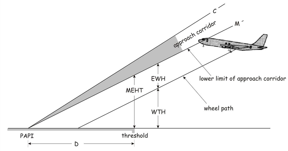
The Minimum Eye Height over Threshold (MEHT) is composed of the Eye to Wheel Height (EWH) and the Wheel to Threshold Height (WTH) [12]. So clearly, in order the ensure compliance with the minimum WTH, the PAPI geometry (distance D, line M) will have to be adjusted for the aircraft dimensions. But which aircraft? ICAO Annex 14 contains an interesting statement regarding that problem:
“Where a PAPI or APAPI is installed on a runway not equipped with an ILS or MLS, the distance […] shall be calculated to ensure that the lowest height at which a pilot will see a correct approach path indication […] provides the wheel clearance over the threshold specified in […] for the most demanding amongst aeroplanes regularly using the runway” [10].
So, caution should be exercised when flying an unusually large aircraft for a specific airport. The PAPI’s MEHT is usually also specified in the Aeronautical Information Publication (AIP).
At this point, I would like to advertise a very informative article written by “Eddie”, on code7700.com. He describes very nicely the differences between aiming point and touchdown point:
Aim Point vs. Touchdown Point (code7700.com, with permission)
So MEHT is one problem. When we add the ILS, there is another complication: The Eye to Antenna Height (EAH). For a standard ILS, the glideslope (i.e., the glideslope antenna of the aircraft) will cross the threshold at 50 ft [12]. Now how does that go together with the PAPI? Well, it does not! A compromise will have to be found, as ICAO Annex 14 proposes:
“Where a PAPI or APAPI is installed on a runway equipped with an ILS and/or MLS, the distance […] shall be calculated to provide the optimum compatibility between the visual and non-visual aids for the range of eye-to-antenna heights of the aeroplanes regularly using the runway” [10].
See Figure 7 below: The yellow sector represents the PAPI “on path” indication. It has to be arranged to comply with the MEHT and as closely as possible with the ILS glideslope. This depends again on the aircraft dimensions (EAH). The dashed lines show the tracks of a pilot’s eyes for different EAH (0-7 m) when following the ILS glideslope.

It is therefore apparent, that the pilot of a very small aircraft will likely see a “below path” indication from the PAPI when getting close to CAT 1 DH. The opposite can happen, when an unusually large aircraft approaches the runway.
When close to the runway, the PAPI indication of an ILS equipped runway should therefore be treated with caution.
Flare…flare…flare…, for how long can we tolerate it?
Every decent pilot will know that extending the flare in order to achieve a “soft” touchdown is absolute non-sense and outright dangerous! The goal of the flare should be to reduce the sink rate to an acceptable level, not to zero. The question is: When is a “long flare” simply “too long”? Here are some “go around triggers”:
Distance #1: End of touch down zone
Many operators mandate a go-around when the touchdown-zone “disappears under the aircraft” while still airborne. That is a good start, but might be insufficient in some cases or not feasible e.g., if the runway is covered in snow and markings are not or barely visible.
Distance #2: OFD+(LDA-FLD) (the magic number)
As depicted in Figure 2, the in-flight landing distance calculation makes use of a “operational (realistic) flare distance” (OFD), as opposed to the “minimalistic flare” of the dispatch calculation. It is therefore very useful for the flight crew to be aware, what the flare distance used for the in-flight calculation actually is. This number is usually published by CS-25 performance applications. If we add the OFD and the landing margin (LDA-FLD), we can estimate a point where a go-around should be initiated. And that might be before the touchdown zone ends! (I call that distance: the magic number.)
Time
Very useful cues are the time since threshold crossing and the flare time. AC25-32 provides guidance for manufacturers to establish the operational (realistic) flare distance and recommends a time of 7 s at Vapp after threshold crossing until touchdown [13]. That leaves about 4-5 s for the flare process, depending on the aircraft size (as the flare does not start at the threshold). So, for a standard setup: If the flare takes longer than 4-5 s, something is not quite right. A useful limit when to consider a go around would be around 7 s for the flare process itself, that might change slightly depending on the circumstances.
Geometry
There are obviously also geometry limits for a safe landing, the maximum pitch angle is the most obvious one with respect to the flare process. The other angle to monitor closely is the angle of attack (AOA), even if not directly indicated. A comparison of pitch and flight path angle may help as an AOA estimation. If the aircraft reaches the critical AOA and is still airborne, a go-around can save the day.
So, we can have to following “or-gate” in our mind during the flare process:

Go around triggers: Do they work in practice?
As an illustrative example, let us look at an accident, where the crew ignored three of the aforementioned “triggers” that would have mandated a go around each on its own. The goal is not to blame anyone, but to see how such an accident can be prevented.
Content is based on the official report [14]:
In 2017, an A320 overran the end of runway 32 in Sylt (EDXW) after landing with a tailwind and a long flare. The wind was 140° 12 kt. To be fair, the ILS approach to runway 32 was the only option, due to a low ceiling and runway 14 only providing a type A approach. The aircraft was approved for up to 15 kt tailwind, the performance calculation is depicted below.
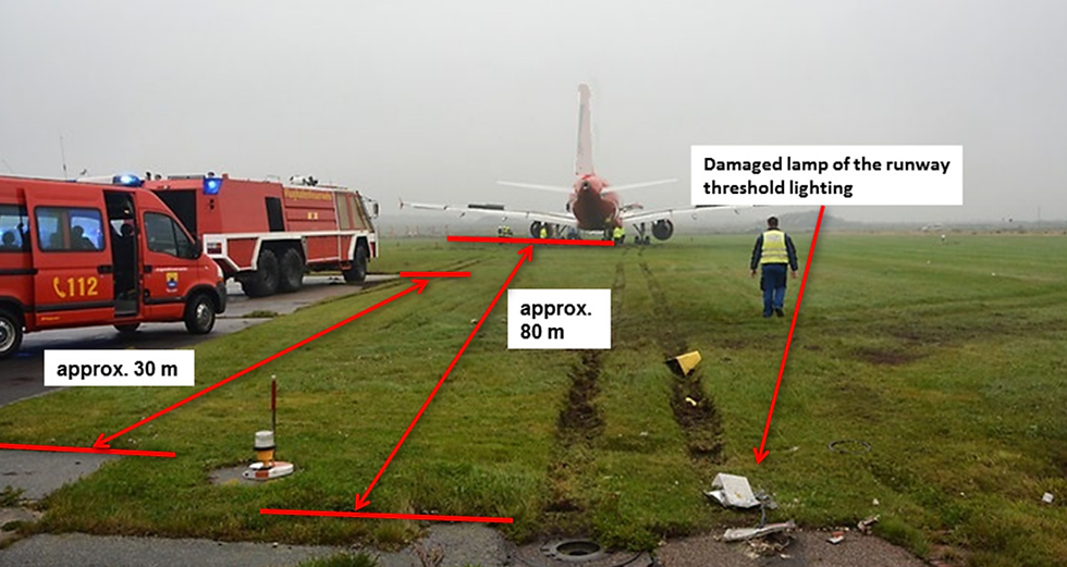
The experienced crew performed an in-flight landing distance calculation using the reported wind, which yielded an FLD of 1990 m with an LDA of 2120 m. It was legal. But it was tight. Figure 10 depicts the reconstructed calculation in the accident report:

The accident report [14] unfortunately confuses dispatch criteria and in-flight criteria, therefore the text of Figure 10 has been slightly modified to reflect the correct terms. Further, the report is silent about the operational flare distance. It must therefore remain open, as to what extent the crew was aware, just how tight it was. Even with that in mind, the calculation showed, that there was only a 130 m margin between the FLD and the LDA. For reasons not determined, the captain even increased the approach speed by another 5 kt during the final approach. No consideration was made with regard to effects of that speed increase on the landing distance. It was clear, that the landing would have to be “spot on” with very little margin for a long flare.
Now let us look at the FDR data: The aircraft travelled 930 m from the threshold until touchdown. The touchdown zone was 600 m long, i.a.w. ICAO standards for that runway length.
Go around trigger #1: The end of the touchdown zone was overflown.
Go around trigger #2: The aircraft also exceeded the magic number: OFD+(LDA-FLD). The report does not mention OFD, it can be estimated to be around 530 m under these conditions. That would result in a magic number of 530 m + (2120 m -1990 m) = 660 m.
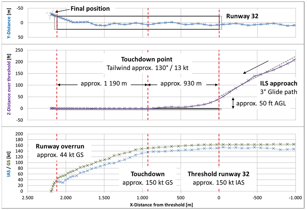
Another important cue would have been the time. It took 12 s from passing the threshold until touchdown, with the radar altimeter twice calling out “five”…
The flare itself lasted for about 10 s.
Go around trigger #3: The flare time exceeded 7 s.
This accident shows once more that there is no amount of experience that would preclude an accident. When it comes to dynamic flight phases such as the landing, it is paramount to have a proper set of limits to judge one’s performance and to initiate a go around when the circumstances warrant it.
In this article we looked at some typical caveats during landing, the list is by no means complete. Of course, there are other factors to consider for a safe landing, such as “stabilized approach” and proper use of deceleration means. The interested reader is directed to FAA AC91-79A [15] for more information.
Revision/20210222
References
[1] EU/EASA, Regulation 965/2012 “EU-OPS”, 2019
[2] AIRBUS, Safety First Magazine, 07/2011
[3] ICAO, State letter 073e “GRF”, 07/2020
[4] ICAO, PANS-ADR doc 9981, 3rd edition, 2020
[5] Federal Republic of Germany, IFR AIC 02/20 National Implementation of the
Global Reporting Format (GRF) for Runway Surface Conditions, 2020
[6] EU/EASA, Regulation 139/2014 “Aerodromes”, 2020
[7] ICAO, PANS-AIM doc 10066, 1st edition, 2018
[8] German Federal Ministry of Transport and Digital Infrastructure, BMVI LF15/6111.4/17, Nationale Implementierung des Global Reporting Format (GRF) for Runway Surface Conditions, 2020
[9] ICAO, Circular 355, Assessment, Measurement and Reporting of Runway Surface Conditions, 2019
[10] ICAO, Annex 14, vol. 1, 8th edition, 2018
[11] ICAO, Annex 10, vol. 1, 6th edition, 2006
[12] Transport Canada, AC 302-009 Precision Approach Path Indicator Harmonization with Instrument Landing System, 2010
[13] FAA, AC25-32 Landing Performance Data for Time-of-Arrival Landing Performance Assessments, 2015
[14] German Federal Bureau of Aircraft Accident Investigation, Investigation Report BFU17-1339-5X, 2020
[15] FAA, AC91-79A Mitigating the Risks of a Runway Overrun Upon Landing, change 2, 2018


